Installing BLTouch Auto-Leveling on the Creality CR-10 V2 and V3
Upgrading your Creality CR-10 V2 or CR-10 V3 with a BLTouch probe for auto-bed leveling will ensure your prints have perfect first layers every time and greatly reduce issues with bed adhesion. Additionally, the BLTouch probe allows better tolerances for slightly warped print beds by measuring and compensating for any inconsistencies. Many premium 3D printers include this feature standard, but fortunately it can also be installed on many lower cost 3D printers as an upgrade.
For more information on why we recommend the BL-touch sensor, refer to our Auto Bed Leveling Guide.
Note: Creality Experts receives a commission for items you purchase from this page, at no additional cost to you. For more information, please see our affiliate link policy.
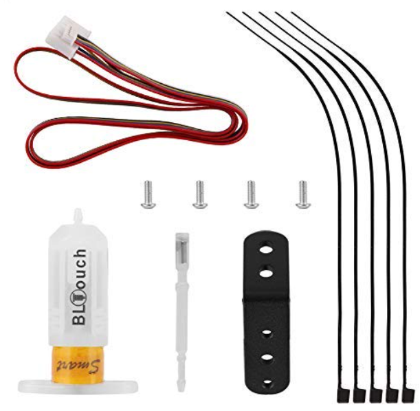
The CR-10 V2/V3 BLTouch kit includes everything you need for the upgrade.
Required Materials
Creality CR-10 V2/V3 BLTouch Upgrade Kit (Amazon link).
Includes:BLTouch sensor
BLtouch cable
Mounting bracket for the CR-10 V2 and V3
Allen wrenches included with printer
How to Install the BLTouch Automatic Bed Leveling Kit on Your CR-10 V2 or V3
Mount the BLTouch sensor to the hot end carriage
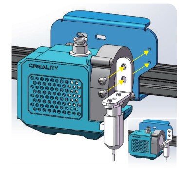
First, you will need to mount the probe on the printer using the provided bracket:
Use the 2 smaller screws included in the kit to mount the BLTouch sensor to the bracket.
Use the 2 longer screws to install the mount to the right of the hot end (there are two holes for this purpose).
Connect the small white port on the cable to the BLTouch sensor. Make sure it is facing the correct direction (it will only fit one way).
Use the included zip ties to route the BLTouch cable along the hot end cable toward the mainboard. This cable runs under the printer towards the mainboard enclosure.
Connect the BLTouch Sensor Cable to the 3D Printer Mainboard
On the Creality CR-10 V2 and V3, the hot end components are connected to a breakout board, so you won’t need to access the mainboard directly. To access the breakout board, you’ll need to remove the cover plate using the three screws shown in the image.

Remove the two screws on top…
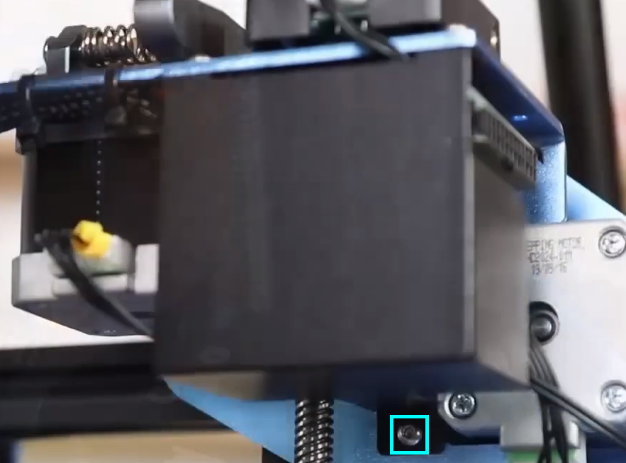
…and one more on the bottom.

The BLTouch port is the unused port closest to you.
Now you can attach the sensor cable to the breakout board:
Disconnect the Z endstop cable.
Plug the cable into the dedicated BLTouch port on the mainboard.
Reattach the enclosure.

Connecting the BLTouch to the dedicated port on the breakout board.
Download 3D printer firmware
Download the corresponding firmware with BLTouch support for your printer from Creality’s site: https://www.creality.com/download
(Note: be sure the version in the firmware file name matches the printed version number on the mainboard).Find the .hex file using the images below.
CR-10 V2

Download the firmware package from https://www.creality.com/download.

Open the folder for the BLTouch firmware.
CR-10 V3
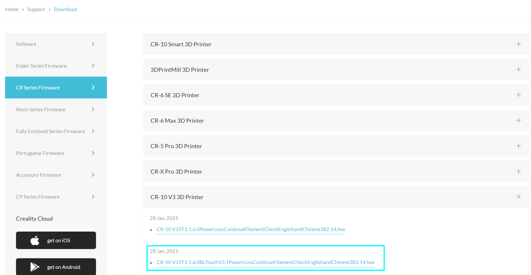
For the V3, the hex file is a standalone download.
Update 3D printer firmware via USB connection
Turn your printer on and connect it to your computer via USB.
Using PrusaSlicer (Cura has a similar feature as well), open the Firmware Flasher tool.
Select the file you downloaded, and the COM port for your 3D printer (it will typically be COM2 or greater).
Click Flash to perform the update.

Open the firmware flash tool.

Configure the tool to connect to your printer and use the correct file.
Calibrate the Z Offset for the BLTouch Probe
The updated printer firmware will allow you to set the Z offset, which controls the position that the printer considers to be “0” directly on the print bed. Follow these steps to calibrate the offset:
Auto home the 3D printer.
Select Control » Initialize EEPROM.
Place a sheet of paper under the nozzle, then move the Z position (Prepare » Move Axis » Move Z) until you can feel resistance on the paper but you can still move it. Write down the ending value (it may be negative).
Navigate to Control » Motion » Z Offset. Adjust the value by the recorded amount (for example, if the recorded value is -.4, adjust the value to be .4 less than the current value. If the current offset is 0, just set it to -.4).
Under Control, select Store Settings to save the offset.
Power the printer off and back on, then auto home the printer, and verify that the nozzle is positioned correctly.
In the same menu, select Disable Stepper to unlock the motors, and repeat the leveling process at each corner (just like standard leveling).
Move the nozzle to a corner of the bed.
Place your sheet of paper and adjust the leveling knob until you feel some resistance when moving the paper.
Repeat on each corner.
Now that the bed is level, fine tune your Z offset by repeating steps 3-5.
Replace the Gcode “G28” in your slicer’s starting script with “G28 G29” to run mesh bed leveling before each print.
You are now ready to run a test print! We recommend testing with a model that has a large footprint to make sure the leveling is correct. If you notice that the first layer is too high or too low, you can “live adjust” the Z offset in the Tune menu if you notice that the first layer of your test print is too high or too low. Any changes you make here will persist for future prints as well.